|
Step
|
Procedure
|
Picture
|
|
76
|
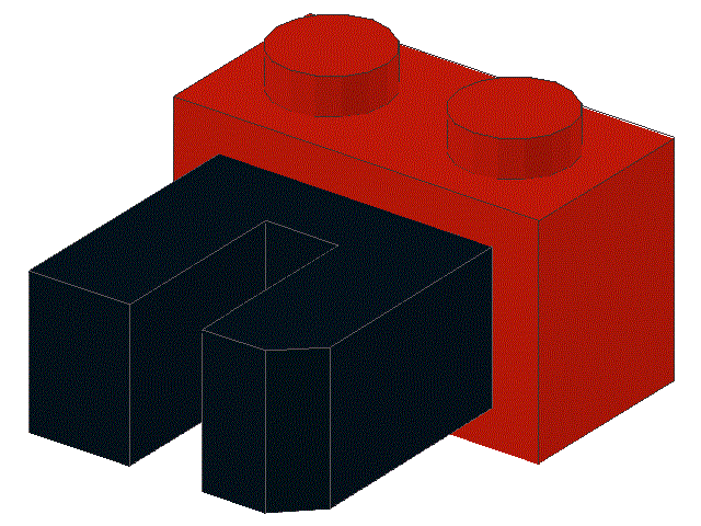
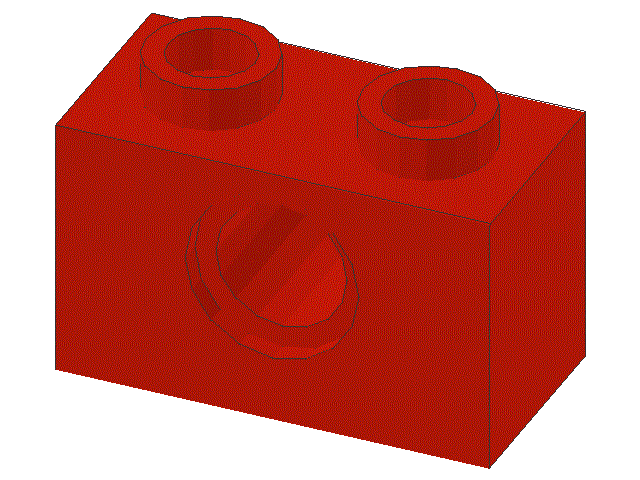
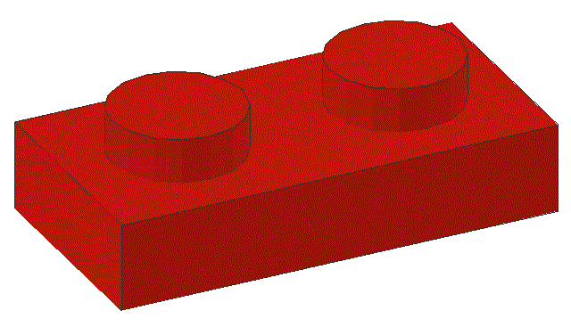
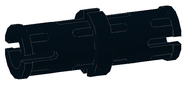
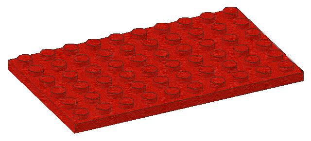
Locate one ,
one ,
and three
|
|
|
77
|
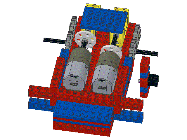
Snap the 1 x 2 plates, the 1 x 2 beam, and the shaft encoder sensor
together to form an assembly, as shown
|
|
|
78
|
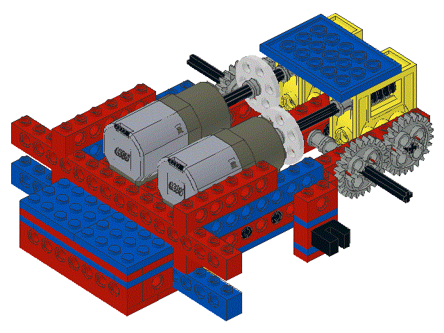
Install the assembled shaft encoder assembly as shown.
Note that the shaft encoder disk may have to be moved a small amount
to ensure that it does not touch the sensor as it rotates.
|
|
|
79
|
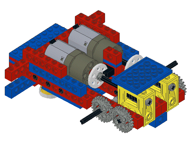
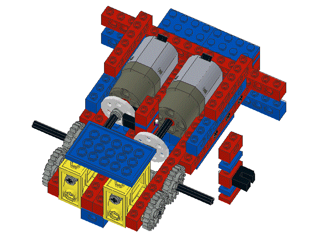
Locate one ,
one ,
and three
|
|
|
80
|
Snap the 1 x 2 plates, the 1 x 2 beam, and the shaft encoder sensor
together to form an assembly, as shown
|

|
|
81
|
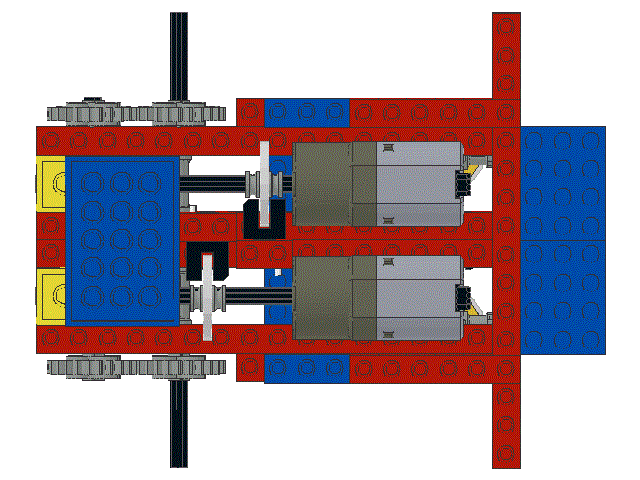
Install the assembled shaft encoder assembly as shown.
Note that the shaft encoder disk may have to be moved a small amount
to ensure that it does not touch the sensor as it rotates.
|
|
|
82
|
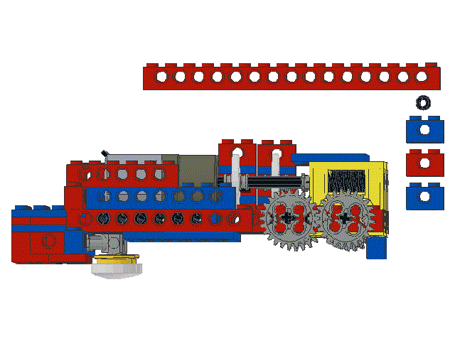
Locate one ,
three ,
and one
|
|
|
83
|
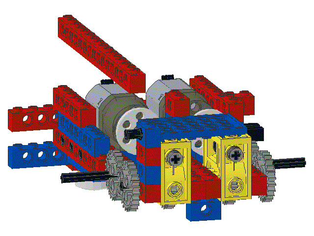
Snap the three 1 x 2 beams togther in a tower configuration and then
insert a black friction peg into the top 1 x 2 beam, as shown
|
|
|
84
|
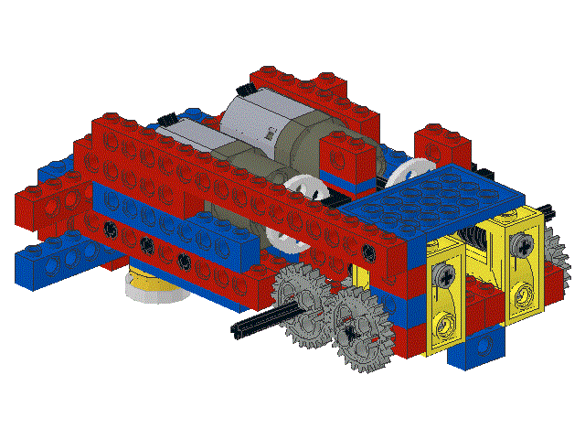
Slide the 1 x 16 beam onto the black friction peg and snap the beam
onto the 1 x 6 beam that was installed in step 75
|
|
|
85
|
Locate one ,
three ,
and one
|
|
|
86
|
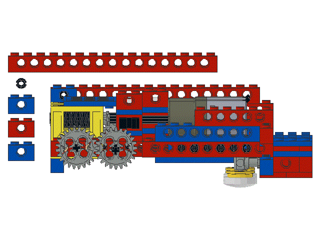
Snap the three 1 x 2 beams togther in a tower configuration and then
insert a black friction peg into the top 1 x 2 beam.
Slide the 1 x 16 beam onto the black friction peg and snap the beam
onto the 1 x 6 beam that was installed in step 75
|

|
|
87
|
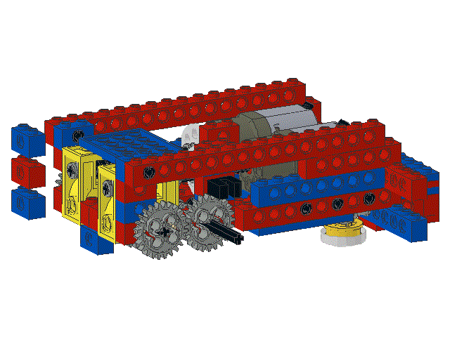
Locate three
|
|
|
88
|
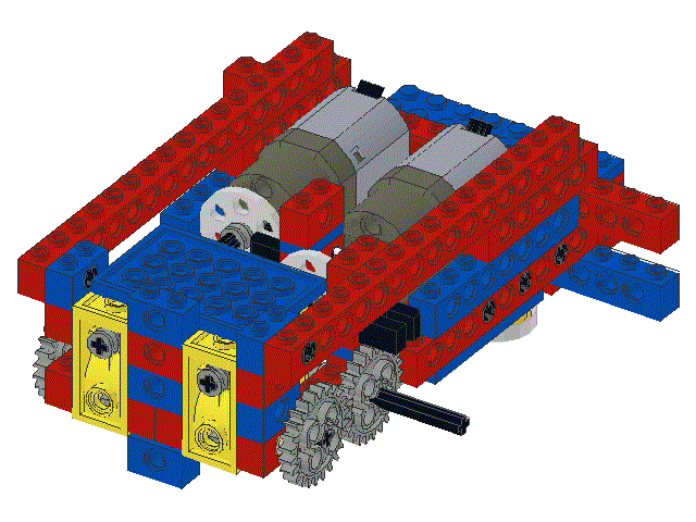
Snap the three 1 x 2 beams into place, as shown
|
|
|
89
|
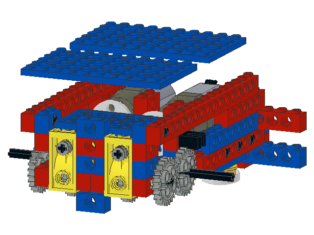
Locate two
|
|
|
90
|
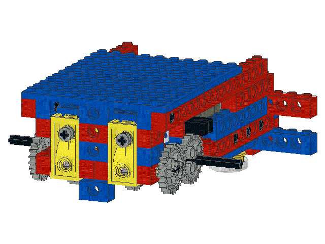
Snap the 6 x 10 plates into place as shown, making sure that
the wires from the shaft encoder sensors are routed through
the gap at the mid-point of the motors.
It may be necessary to gently adjust the tops of the shaft encoder
towers to achieve correct alignment with the plates.
Installing the rear plate first may make the task easier
|
|
