|
Step
|
Procedure
|
Picture
|
|
1
|
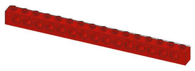
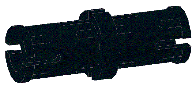
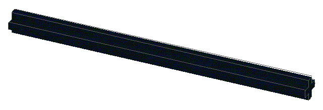
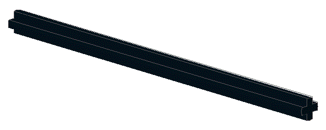
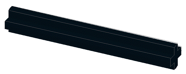
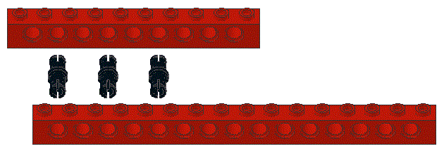
Locate one ,
one ,
and three
|
|
|
2
|
Insert the three black friction pegs in the 1 x 10 beam
in the locations shown
If you accidentally put a peg in the wrong hole, the easiest
way to get it out is to push it out with another peg or an axel
|

|
|
3
|
Snap the 1 x 16 beam and the 1 x 10 beam together
|

|
|
4
|
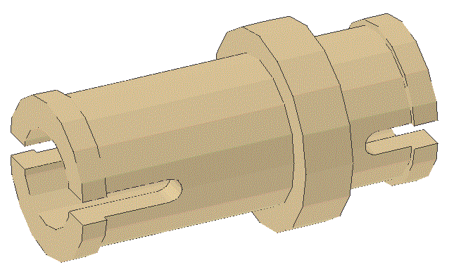
Locate two
|

|
|
5
|
Insert the two brown, tan, or dark grey butt pegs in the 1 x 16 beam
in the locations shown
|

|
|
6
|
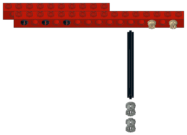
Locate an
two
|
|
|
7
|
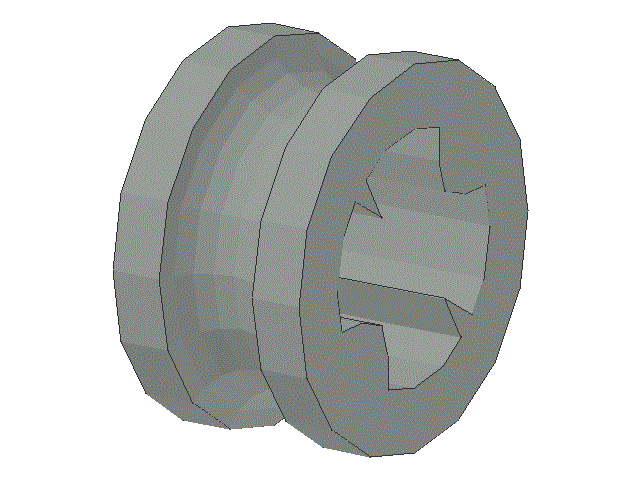
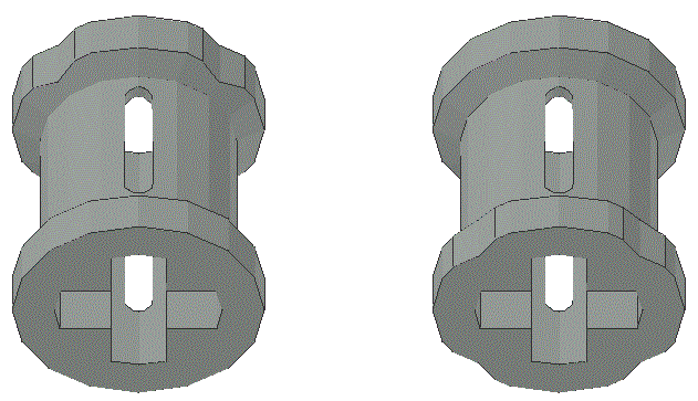
Examine the two ends of the collar carefully.
Note that one end is a smooth circle while the other end is "crinkly"
|
|
|
8
|
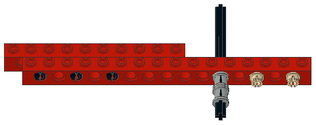
Slide the two collars onto the axel and slide the axel through
the hole in the 1 x 16 beam as shown.
Note that the end of the collar that touches the beam should be the
smoothly circular end - not the "crinkly" end.
This is because, as the axel rotates when the finished robot is moving,
the circular end will rub more smoothly against the beam and cause
minimal wear and scratching of the beam.
For similar reasons, orientate the other collar the opposite way
around - with its smoothly circular end outermost.
In the next step you will see how to align the collars at the proper
place along the axel
|
|
|
9
|
The axel should be aligned so that it has just a very little bit less
than the width of one beam exposed at the end where the collars are.
The picture shows how a Lego beam can be used to help judge this
alignment.
The yellow piece shown is just used tempararily and will not become
part of the robot
|

|
|
10
|
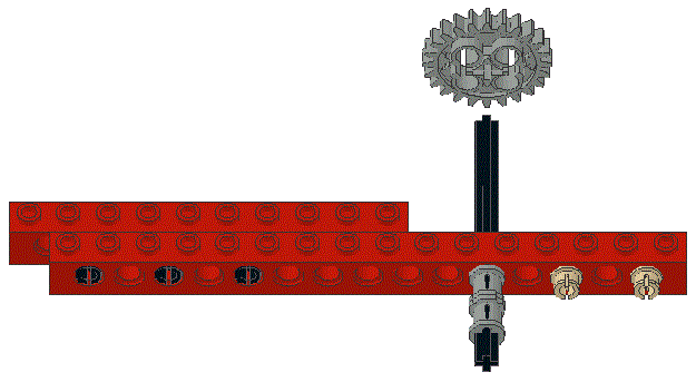
Locate a
|
|
|
11
|
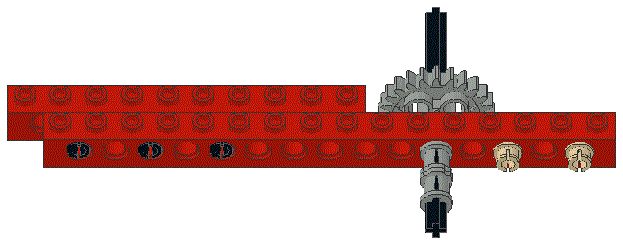
Install it on the axel and slide it tward the 1 x 16 beam, as shown.
The gear should be positioned such that the axel can rotate smoothly
and without and resistance, but the axel should have as little free
motion laterally (along its length) as posible.
|
|
|
12
|
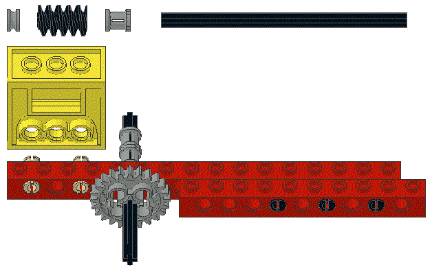
Locate one of each of the following: ,
,
,
,
and .
See the step below to determine the differences between a spacer
and a small pulley
|
|
|
13
|
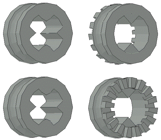
At first glance a spacer (p/n 4265c) and a small pulley (p/n 4265b)
look quite similar.
The picture shows both; the pieces on the left are spacers while the
pieces on the right are small pulleys
|
|
|
14
|
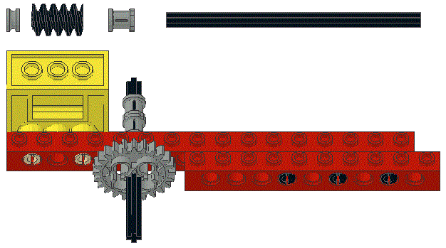
Snap the gearbox to the brown, tan, or dark grey butt pegs protruding from the 1 x 16 beam
|
|
|
15
|
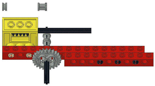
Insert the worm gear into its cavity in the gearbox and slide the axel
into place to lock the worm gear in place
|
|
|
16
|
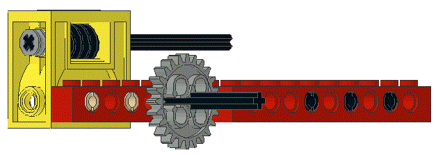
Slide the spacer onto the short end of the axel
|
|
|
17
|
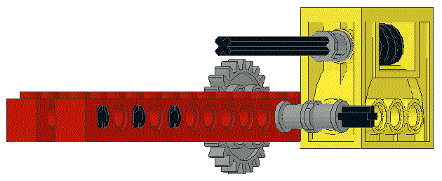
Slide the collar onto the long end of the axel.
The axel should turn smoothly and easily with as little longitudinal
(along the length of the axel) movement as possible.
Note that the smooth circular end of the collar should be toward
the gearbox.
|
|
|
18
|
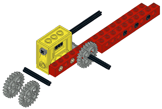
Locate one and
two
|
|
|
19
|
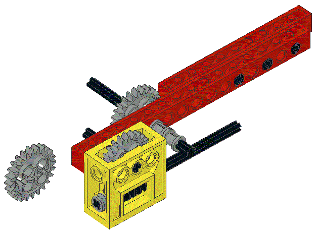
Install a 24-tooth gear inside the gearbox and slide the axel
through the gearbox and gear to lock the two together
One end of the axel should be flush with the exposed side of the gearbox
with its other end protruding through the 1 x 16 beam
|
|
|
20
|
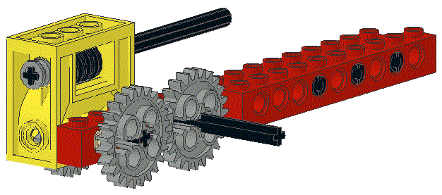
Slide a 24-tooth gear on the exposed end of the axel.
Ensure that there is enough clearance between the gear and the 1 x 16
beam to allow the gear to rotate freely and smoothly
Note that the gears can only be rotated by using the axel to turn the worm gear.
Also note that the gear rotates one 24th of turn for every complete turn of the worm gear
and that the axel through the worm and the axel through the gear are perpendicular
|
|
|
21
|
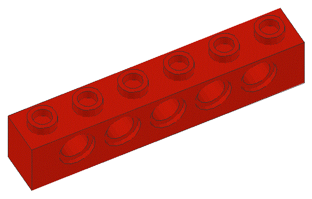
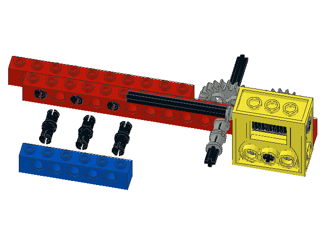
Locate one
and three
|
|
|
22
|
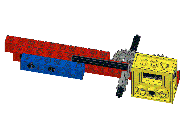
Snap the 1 x 6 beam and the 1 x 16 beam together as shown
|
|
|
23
|
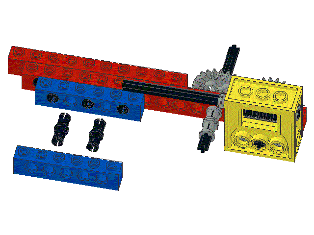
Locate another
and two more
|
|
|
24
|
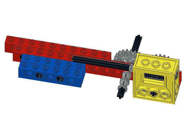
Snap the two 1 x 6 beams together as shown
|
|
|
25
|
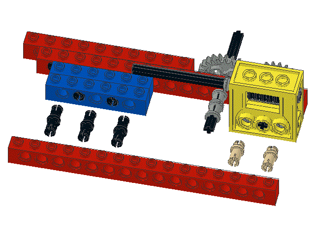
Locate two ,
three ,
and one
|
|
|
26
|
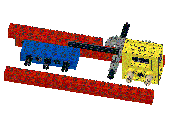
Snap the two brown, tan, or dark grey butt pegs into the gearbox
and snap the three black friction pegs into the 1 x 6 beam as shown
|
|
|
27
|
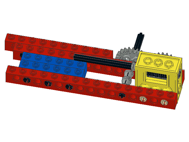
Making sure that the axel slides easily into the appropriate hole
in the 1 x 16 beam, snap the beam onto the two brown, tan, or dark grey butt pegs,
and the three black friction pegs, as shown
|
|
