AndyBoard Autonomous Robotics: Basics

AndyBoard - April 2024 - Lab 1 - A Basic Robot - Part 2: Steps 28 thru 50

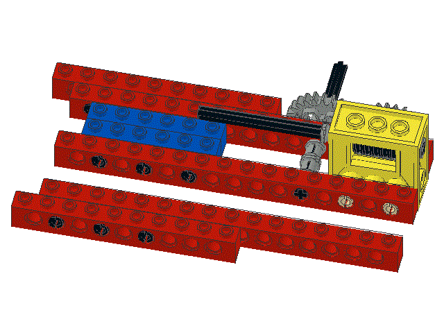
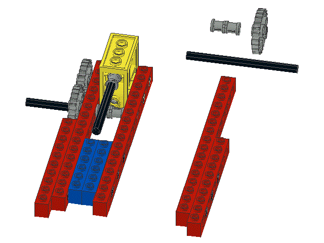
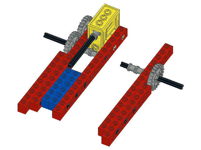
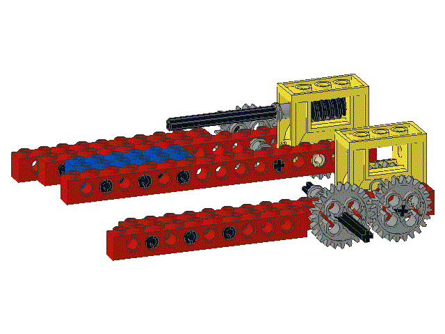
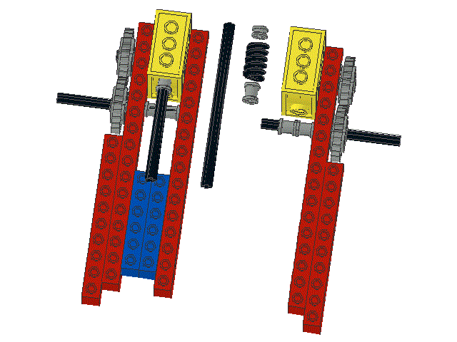
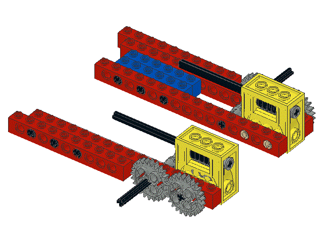
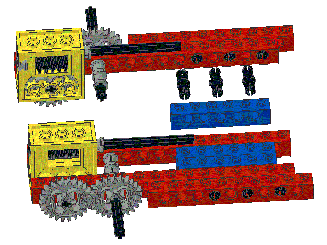
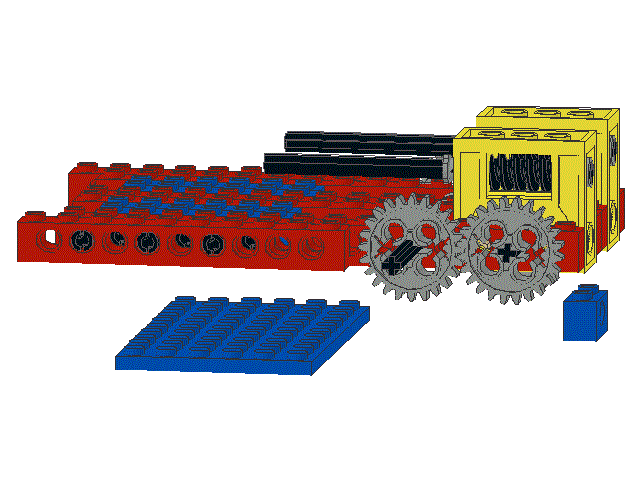
Follow the steps below to build the left half of the main chassis and join the left and right halves together.

Step Procedure Picture
28 Locate one
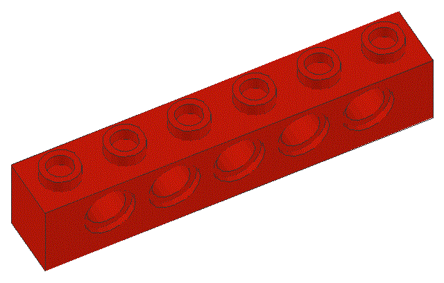
1 x 16 beam (p/n 3703)
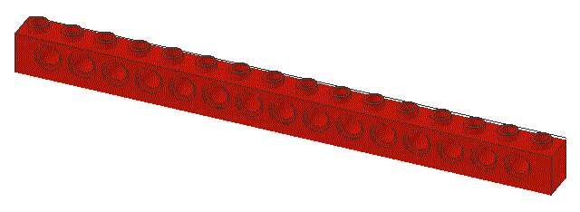
, one
1 x 10 beam (p/n 2730)
, and three
black friction pegs (p/n 2780)
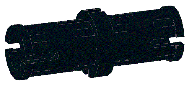
29 Insert the three black friction pegs into the 1 x 16 beam in the locations shown and then snap it together with the 1 x 10 beam
30 Locate one
8 unit long axel (p/n 3707)
, two
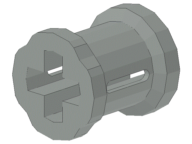
collars (p/n 3713)
, and one
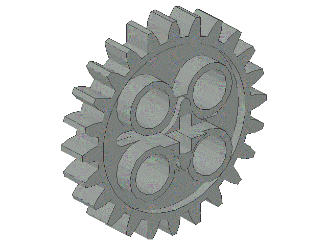
24-tooth gear (p/n 3648)
31 Assemble the axel, collars, and 24-tooth gear as shown. Remember to orient the collars correctly (so as to reduce wear and damage to rotating surfaces)
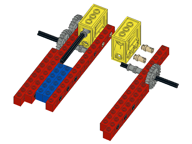
32 Locate two
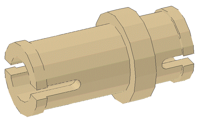
brown, tan, or dark grey butt pegs (p/n 32002)
and one
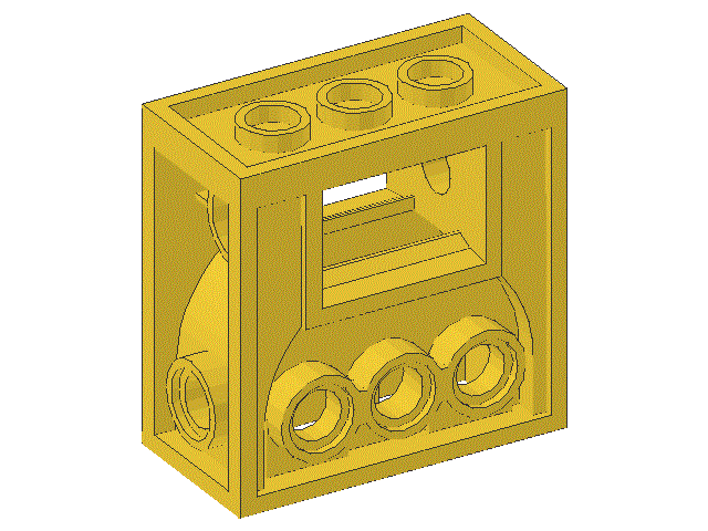
gearbox (p/n 6588)
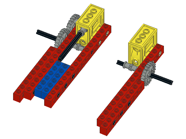
33 Insert the two brown, tan, or dark grey butt pegs in the 1 x 16 beam at the loactions shown and snap the gearbox to the butt pegs
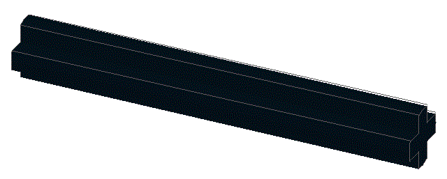
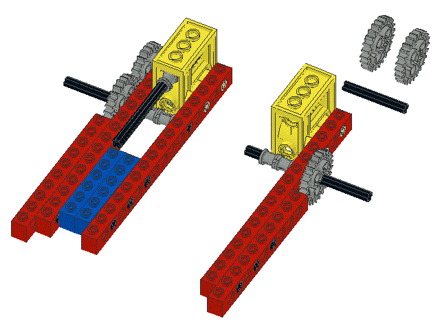
34 Locate one
four unit axel (p/n 3705)
and two
24-tooth gears (p/n 3648)
35 Insert one of the 24-tooth gears into the gearbox, insert the axel as shown, and slide the second 24-tooth gear onto the axel
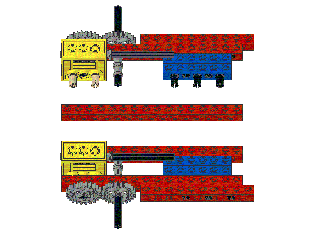
36 Locate one of each of the following:
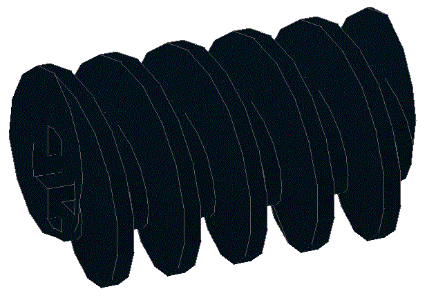
worm gear (p/n 4716)
,
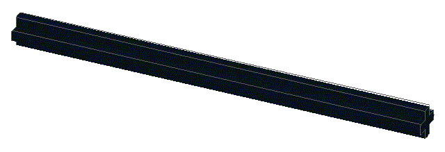
10 unit axel (p/n 3737)
,
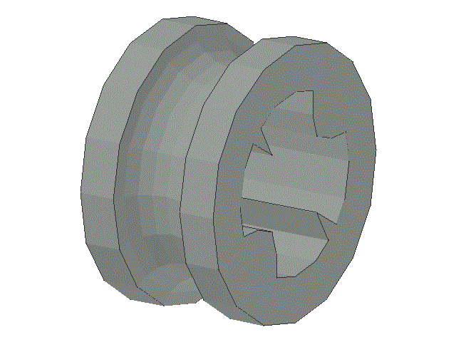
collar (p/n 3713)
, and
spacer (p/n 4265c)
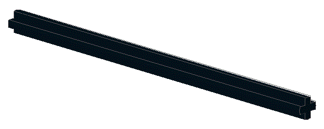
37 Insert the worm gear into its cavity in the gearbox and slide the axel into place to lock the worm gear in place. Slide the spacer onto the short end of the axel. Slide the collar onto the long end of the axel. The axel should turn smoothly and easily with as little longitudinal movement as possible. Note that the smooth circular end of the collar should be toward the gearbox.
38 Locate one
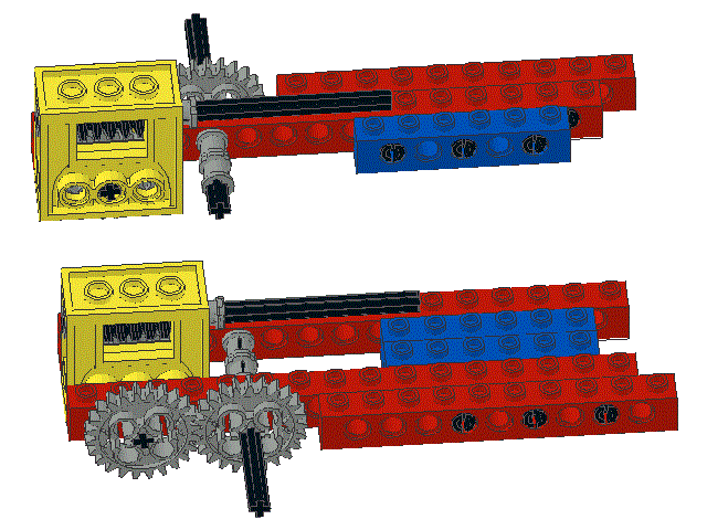
1 x 6 beam (p/n 3894)
, and three
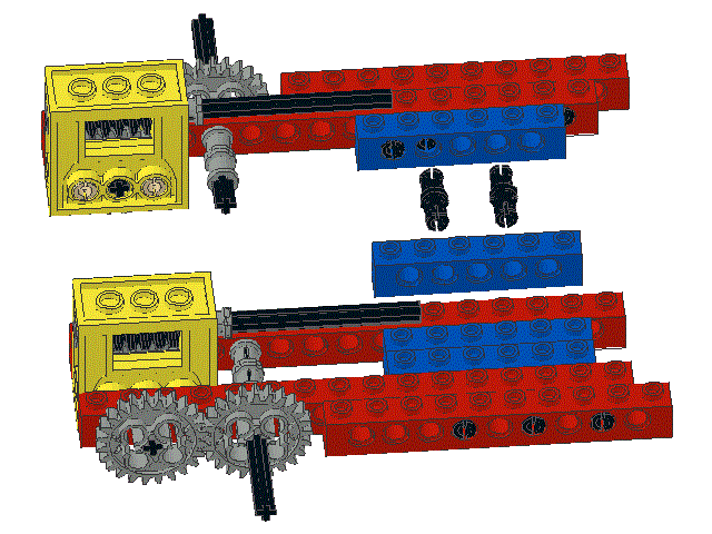
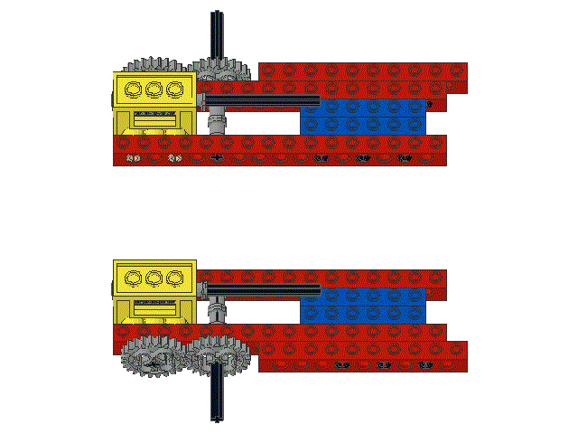
black friction pegs (p/n 2780)
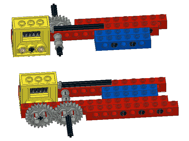
39 Snap the 1 x 6 beam and the 1 x 16 beam together as shown
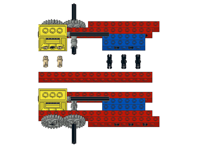
40 Locate another
1 x 6 beam (p/n 3894)
, and two more
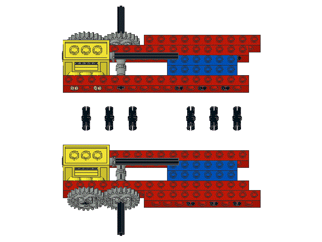
black friction pegs (p/n 2780)
41 Snap the two 1 x 6 beams together as shown
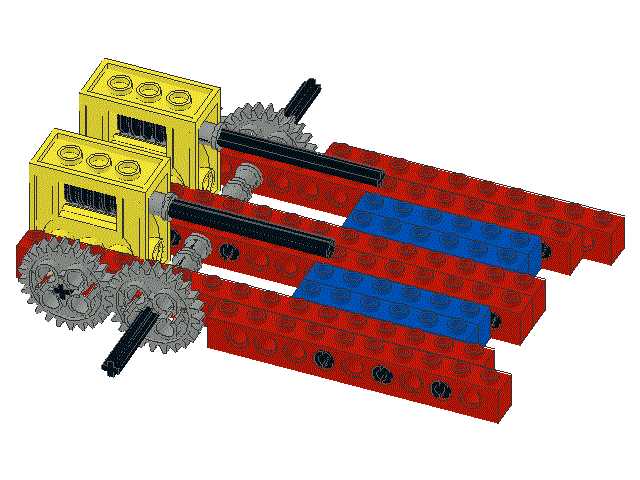
42 Locate two
brown, tan, or dark grey butt pegs (p/n 32002)
, three
black friction pegs (p/n 2780)
, and one
1 x 16 beam (p/n 3703)
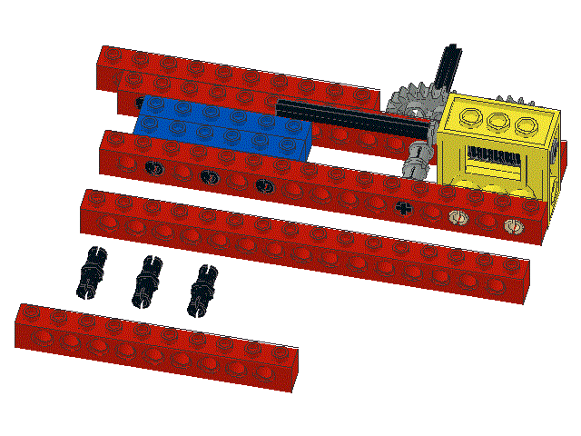
43 Snap the two brown, tan, or dark grey butt pegs into the gearbox and snap the three black friction pegs into the 1 x 6 beam as shown
44 Making sure that the axel slides easily into the appropriate hole in the 1 x 16 beam, snap the beam onto the two brown, tan, or dark grey butt pegs, and the three black friction pegs, as shown
45 Locate six
black friction pegs (p/n 2780)
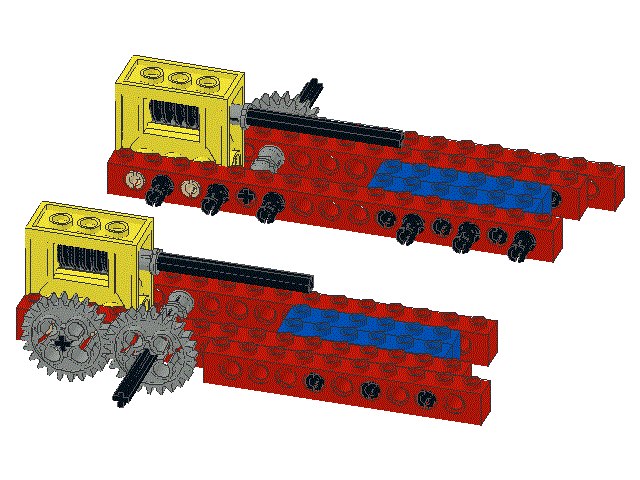
46 Snap the six black friction pegs into the indicated holes in the 1 x 16 beam.
47 Snap the two central 1 x 16 beams together. Make sure that the crosswise axels rotate freely without touching each other or any friction pegs
48 Locate one
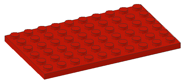
6 x 10 plate (p/n 3033)
and one
1 x 2 beam (p/n 3700)
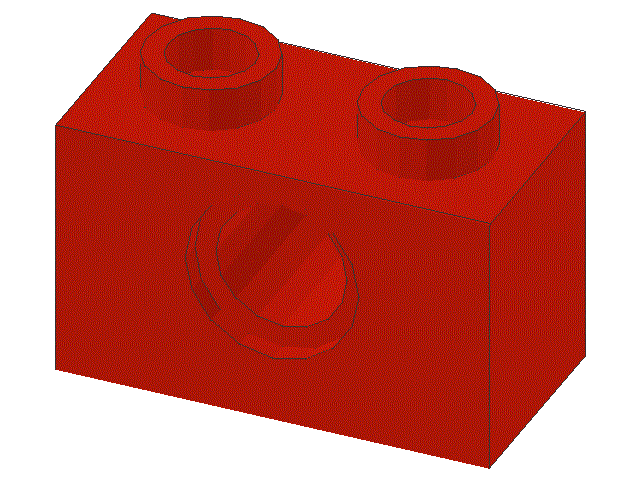
49 Snap the 6 x 10 plate and the 1 x 2 beam onto the underneath of the chassis in the locations shown
50 Locate a
4 x 6 plate (p/n 3032)
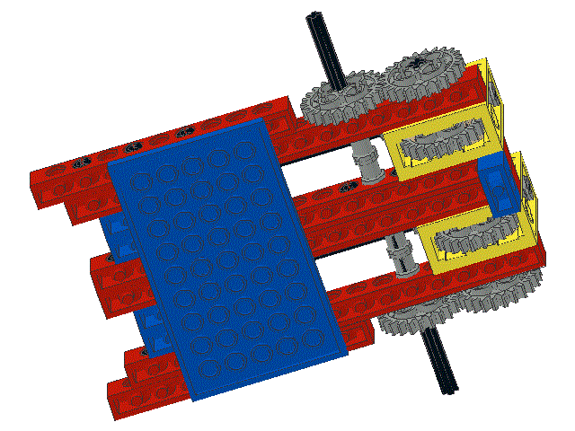
and snap it onto the top of the gearboxes in the position shown.
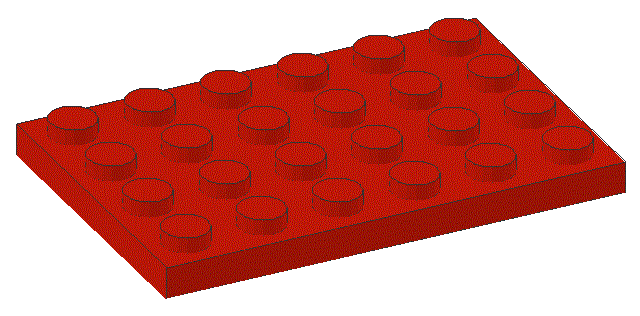
Note that the plate is located with one row of Lego buttons in front (left) of the gearboxes

Also note that the plate is upside-down with respect to the robot.
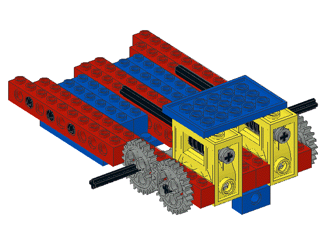

That completes construction of the left half of the main chassis and the linking of it to the right hand half.

Please use your browsers "BACK" button to return to the previous screen and then proceed to Part 3

updated 20jan19 AC