AndyBoard Autonomous Robotics: Basics |
AndyBoard - April 2024 - Lab 1 - A Basic Robot - Part 3: Steps 51 thru 55
Follow the steps below to install the motors and the shaft encoder disks.
Step | Procedure | Picture |
51 |
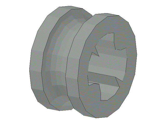
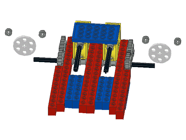
Locate four spacers (p/n 4265c) ,
and two shaft encoder disks
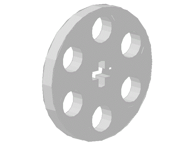
Note that the shaft encoder disks are flat, approximately 1" diameter by 0.050" thick, perforated aluminum disks. They may contain more holes and the holes may be a different shape than in the disks shown here | |
52 |
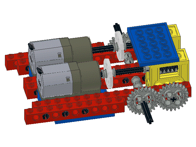
With a spacer on each side of each disk, slide the shaft encoder disks onto the axels as shown.
Because the spacers rotate with the disk, it does not matter whether it is the crinkly or smooth end of the spacer that touches the disk | |
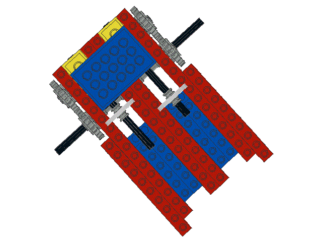
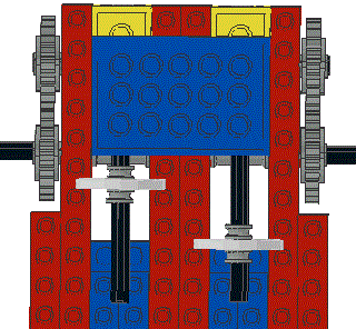
53 | Position the shaft encoder disks as shown in this overhead view. The exact positioning of these disks is important because they must rotate freely within the shaft encoder sensor assembly that you will build in a later step | |
54 |
Locate two Lego Power Functions M-Motors (p/n 8883)
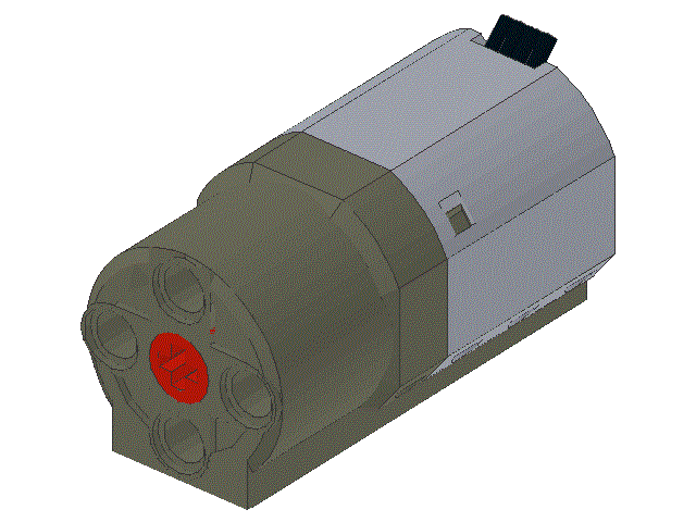
The motors in your kit may look slightly different and may be a slightly different color | |
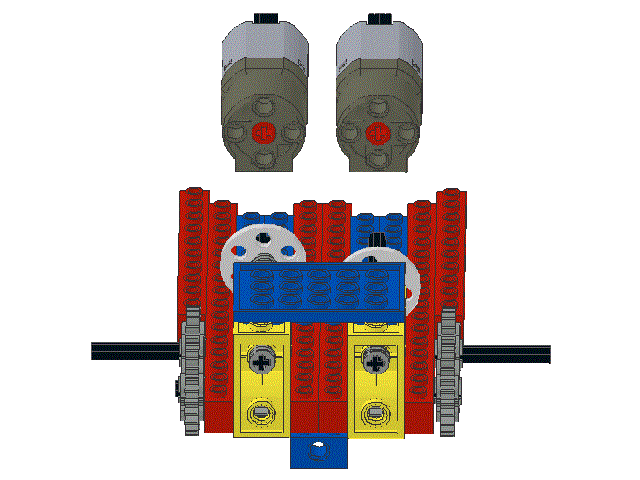
55 | Slide the axels coming from the gearboxes into the front of the motors and then snap the motors onto the 1 x 6 beams that were installed in steps 21 through 24 and steps 38 through 41 |
That completes the installation of the motors and the shaft encoder disks.
Please use your browsers "BACK" button to return to the previous screen and then proceed to Part 4
updated 04jan19 AC