|
Step
|
Procedure
|
Picture
|
|
91
|
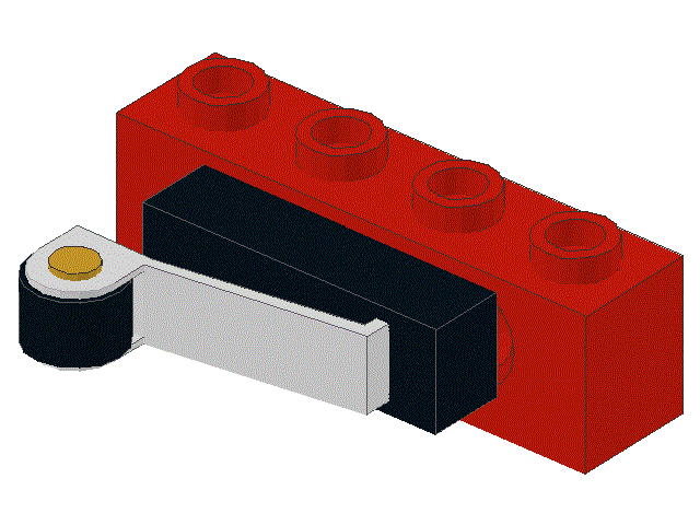
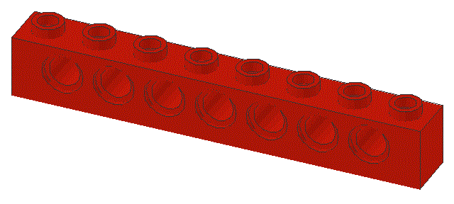
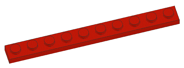
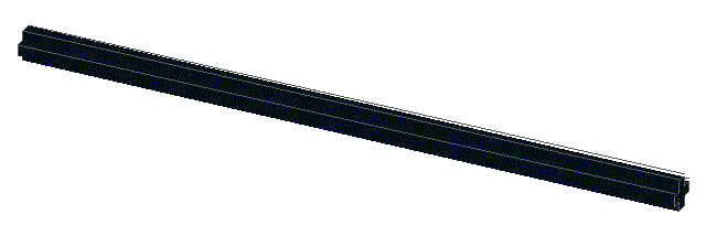
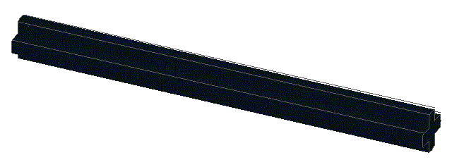
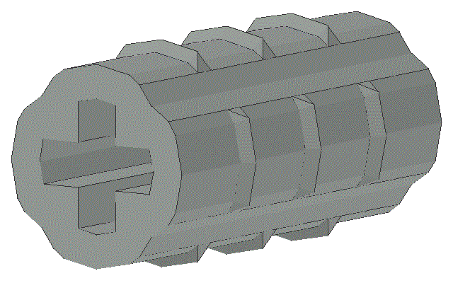
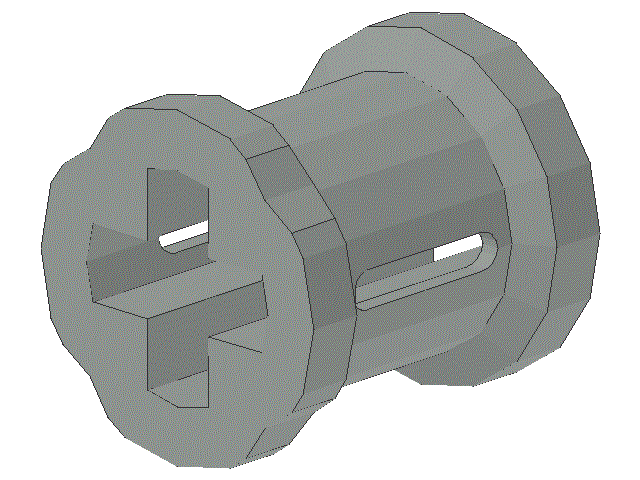
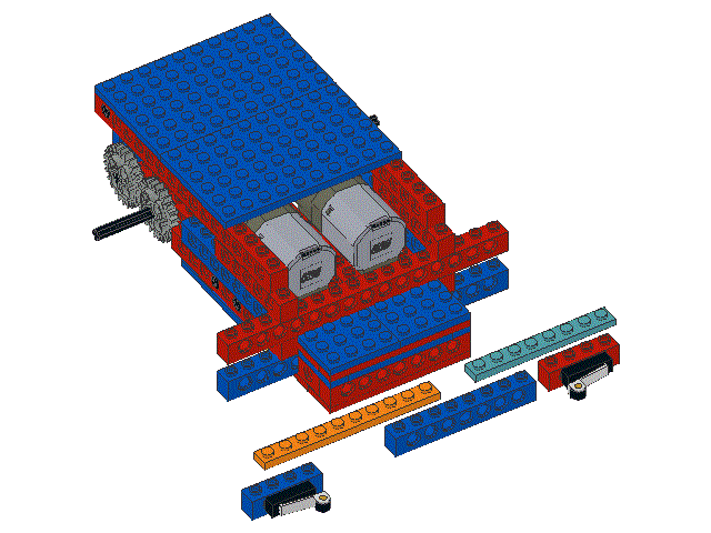
Locate one ,
one ,
one ,
one ,
and one
|
|
|
92
|
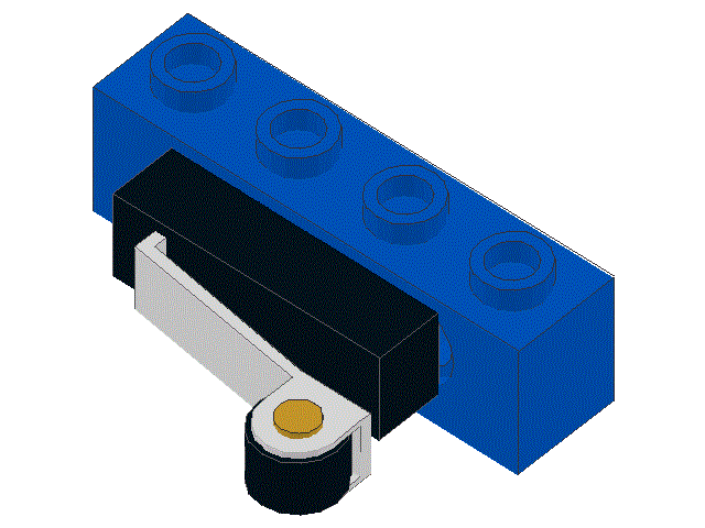
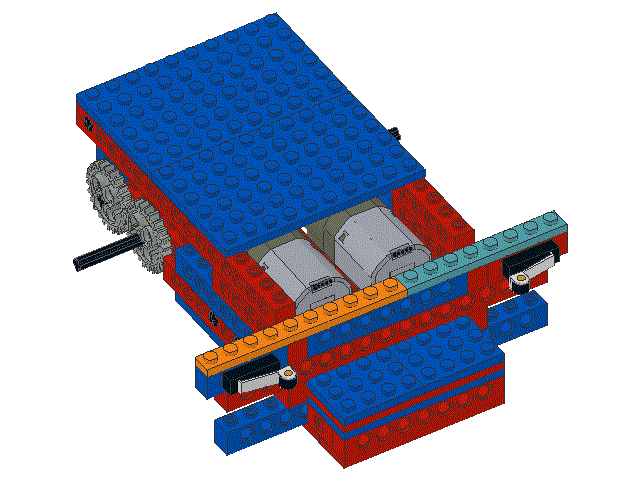
Snap the bump sensors and the 1 x 8 beam into place as shown,
and then snap the 1 x 10 plate and the 1 x 8 plate into place.
|
|
|
93
|
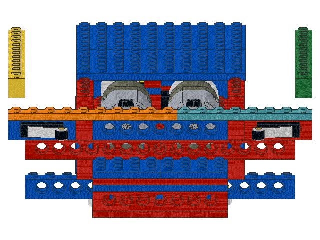
Locate two
|
|
|
94
|
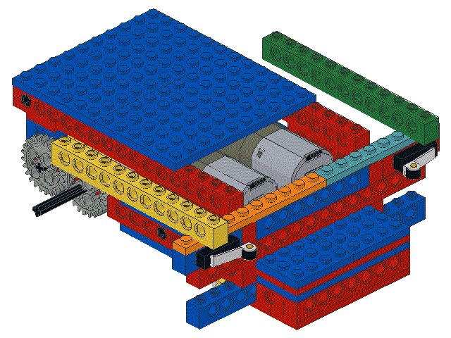
Snap the two 1 x 12 beams into the locations shown
|
|
|
95
|
Locate one ,
two ,
and two
|

|
|
96
|
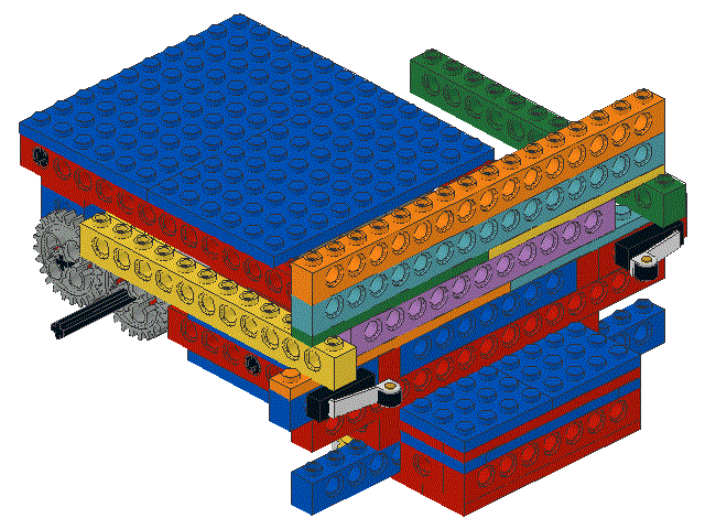
Snap the 1 x 12 beam into place as shown.
Then on snap the two 1 x 8 plates and then the two 1 x 16 beams
|
|
|
97
|
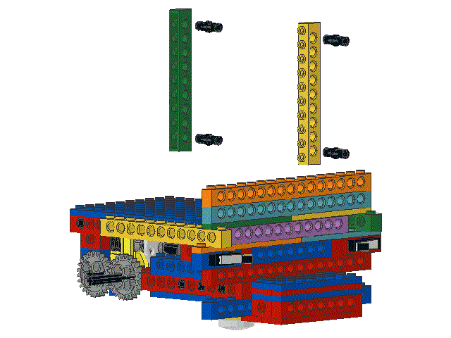
Locate two
and four
|
|
|
98
|
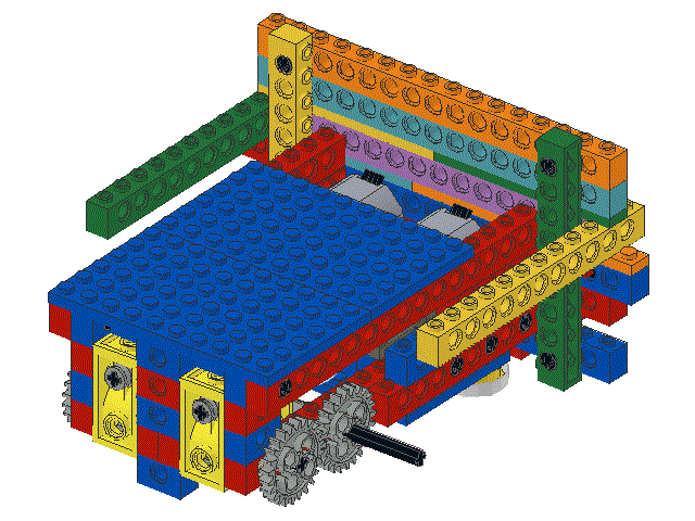
Snap the black friction pegs and the 1 x 10 beams into place as shown.
Note how the beams run perpendicular to the rest of the beams.
The effect of this is to lock the other beams into place,
making the robot robust while keeping it light
|
|
|
99
|
Locate two
and two
|
|
|
100
|
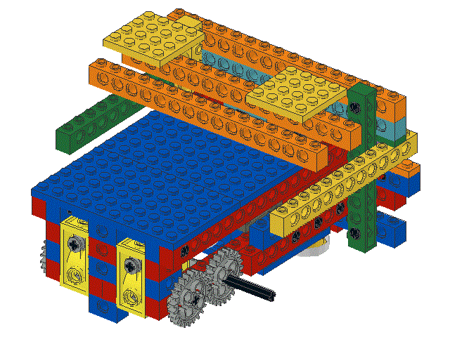
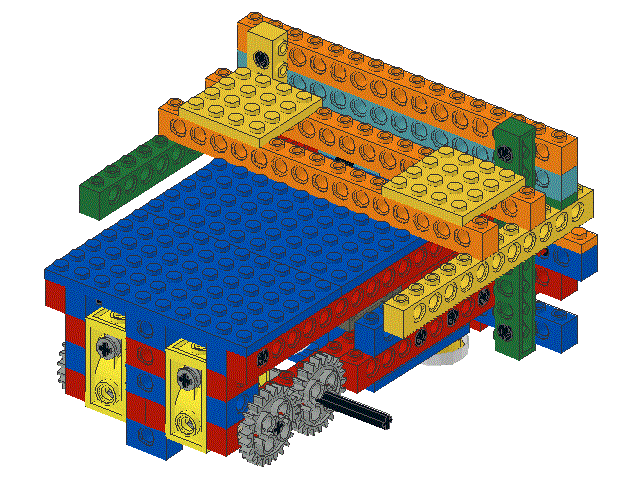
Snap the two 1 x 16 beams into place as shown
and then snap the two 4 x 4 plates onto them.
Note that all the wires from the sensors and motors rise up in front
of both of these 1 x 16 beams.
Also note that the wires from the motors and the shaft encoder sensors
pass under both these beams
|
|
|
101
|
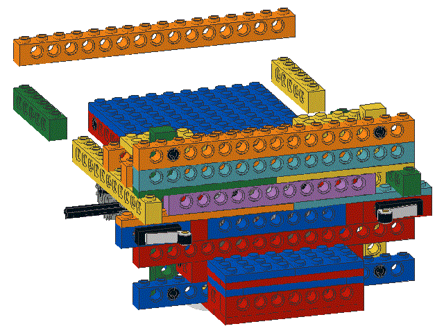
Locate one
and two
|
|
|
102
|
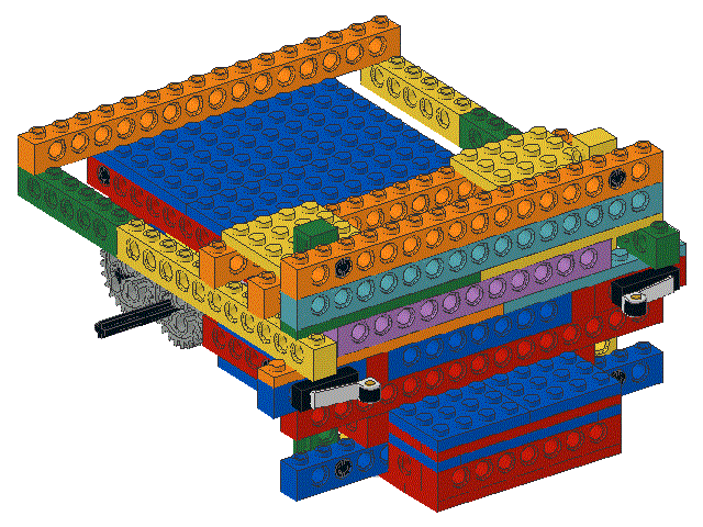
Snap the 1 x 16 beam onto the back decking as shown
and then snap the two 1 x 6 beams on from below
|
|
|
103
|
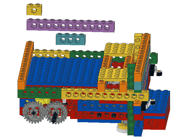
Locate one ,
one ,
and one
|
|
|
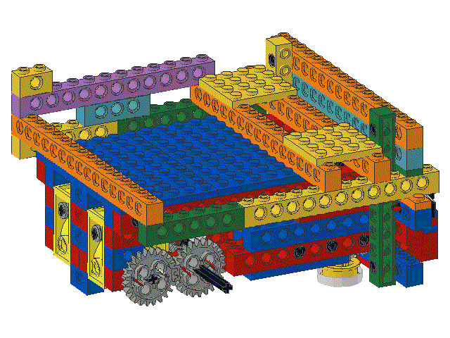
104
|
Snap the 1 x 4 beam on at the junction of the the 1 x 12 and 1 x 6 beams
as shown.
Then snap the 1 x 12 and the 1 x 2 beams into place
|
|
|
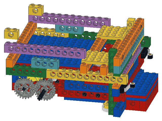
105
|
Locate one ,
one ,
and one
|
|
|
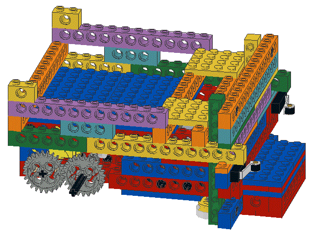
106
|
Snap the 1 x 4 beam on at the junction of the the 1 x 12 and 1 x 6 beams
as shown.
Then snap the 1 x 12 and the 1 x 2 beams into place
|
|
|
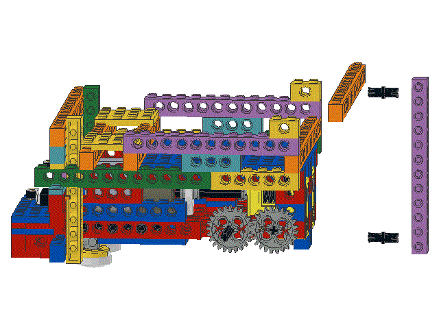
107
|
Locate one ,
one ,
and two
|
|
|
108
|
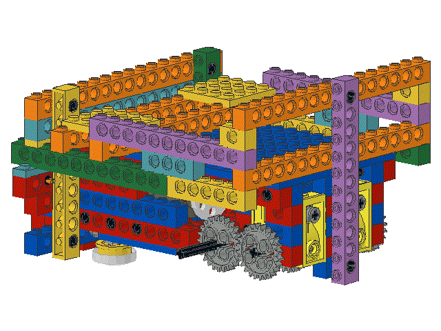
Snap the 1 x 16 beam onto the 1 x 2 beams installed in steps 104 and 106, as shown.
Then insert the black friction pegs into the holes at the ends of the
1 x 12 beam and snap the beam into place, vertically, as shown.
This is another example of using beams that are perpendicular
to make the structure stronger and more rigid
|
|
|
109
|
Locate two ,
four ,
and two
|
|
|
110
|
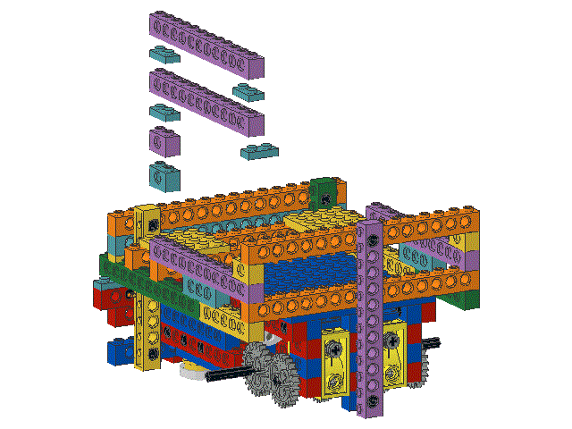
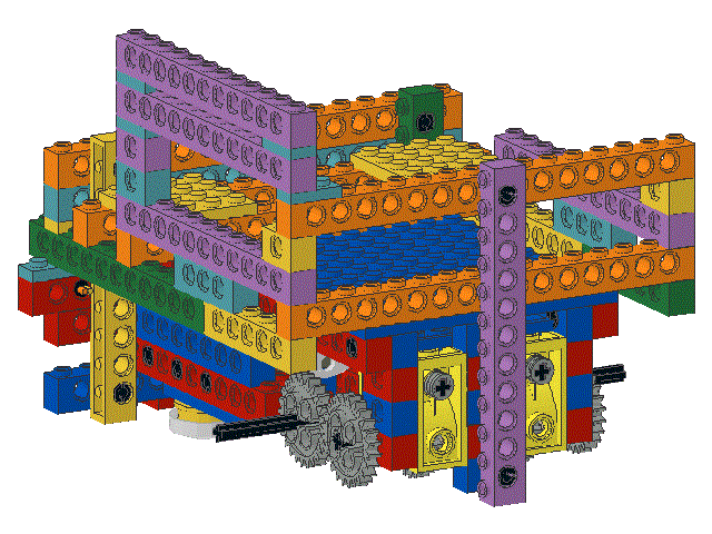
Snap the two 1 x 2 beams into place in a tower as shown.
Snap a 1 x 2 plate onto the top of the 1 x 2 tower.
Snap another 1 x 2 onto the 1 x 16 beam at the back of the robot.
Note that this plate is perpendicular to the other 1 x 2 plate.
Snap a 1 x 12 beam onto the top of the two 1 x 2 plates just added.
Snap two more 1 x 2 plates onto the top ends of the 1 x 12 beam.
Finally, snap a 1 x 12 beam onto the two 1 x 2 plates
|
|
|
111
|
Locate two
and four
|
|
|
112
|
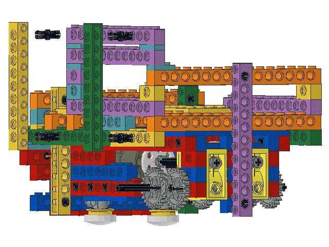
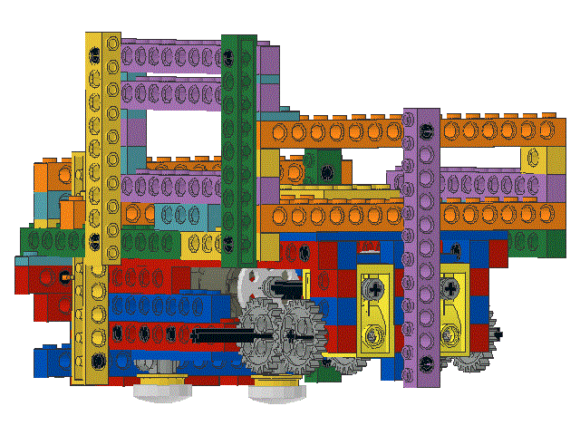
Insert the black friction pegs into the holes at the ends of each
1 x 10 beam and snap the beams into place, vertically, as shown.
|
|
|
113
|
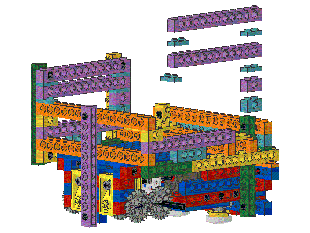
Locate two ,
four ,
and two
|
|
|
114
|
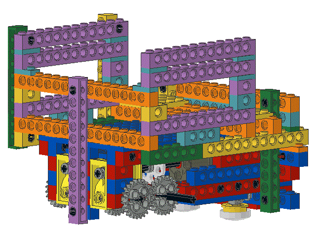
Snap the two 1 x 2 beams into place in a tower as shown.
Snap a 1 x 2 plate onto the top of the 1 x 2 tower.
Snap another 1 x 2 onto the 1 x 16 beam at the back of the robot.
Note that this plate is perpendicular to the other 1 x 2 plate.
Snap a 1 x 12 beam onto the top of the two 1 x 2 plates just added.
Snap two more 1 x 2 plates onto the top ends of the 1 x 12 beam.
Finally, snap a 1 x 12 beam onto the two 1 x 2 plates
|
|
|
115
|
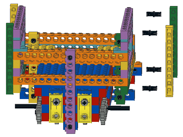
Locate two
and four
|
|
|
116
|
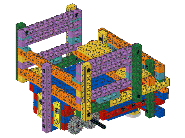
Insert the black friction pegs into the holes at the ends of each
1 x 10 beam and snap the beams into place, vertically, as shown.
|
|
|
117
|
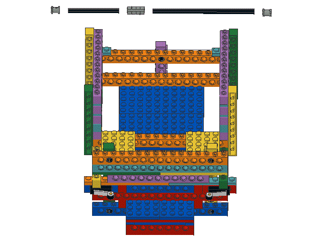
Locate one ,
one ,
one ,
and two
|
|
|
118
|
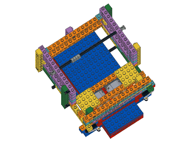
Insert the axels through the top 1 x 12 side beams as shown
and use the coupler to join them.
Slide the collars onto the ends of the axels as shown.
|
|
