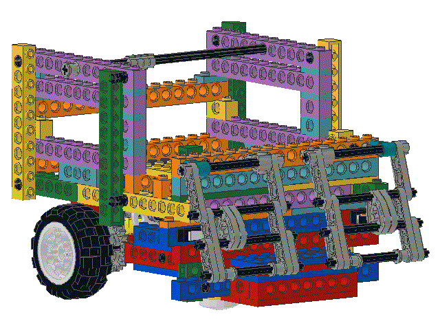
Locate the following parts:
two
splined pegs (p/n 3749) 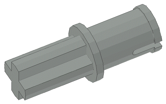
;
two
stanchion tops (p/n 3651 or p/n 32013) 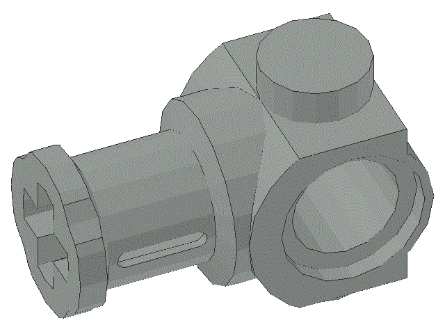
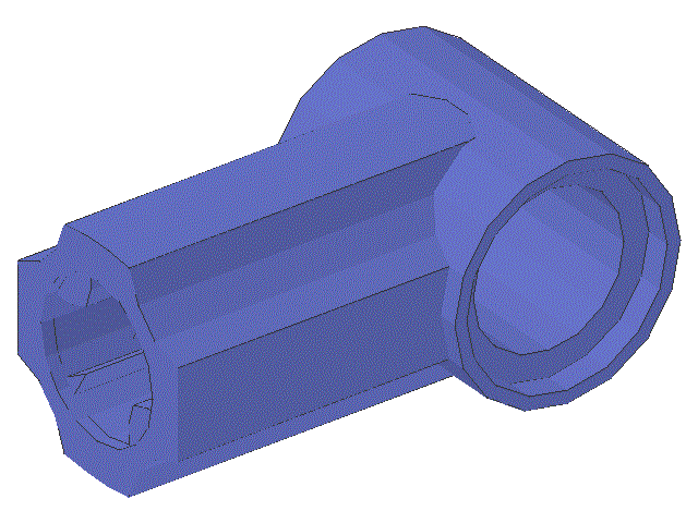
;

two
10 unit long axles (p/n 3737) 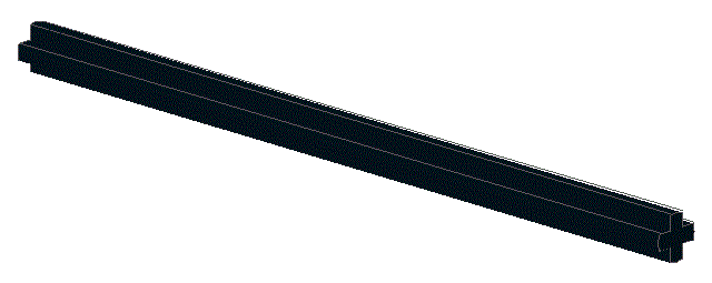
;
two
8 unit long axles (p/n 3707) 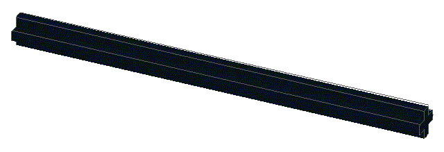
;
three
collars (p/n 3713) 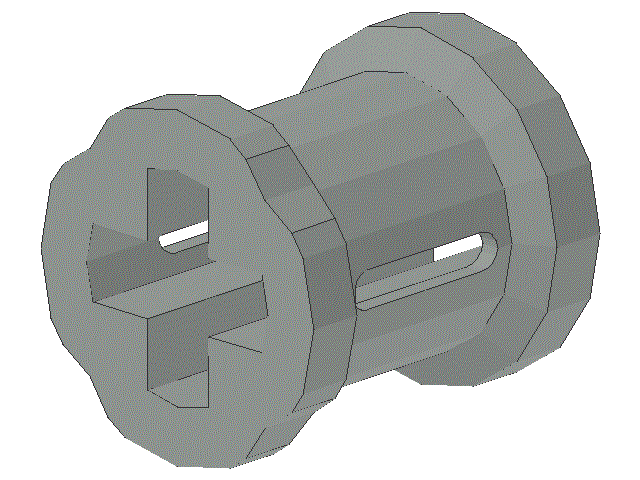
;
two
4 unit long linkages (p/n 2825) 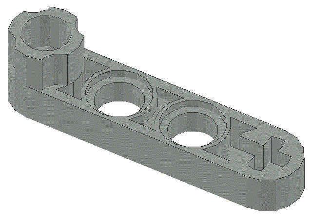
;
two
3 unit long linkages (p/n 6632) 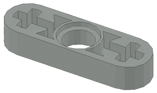
;
two
5 unit long linkages (p/n 32017) 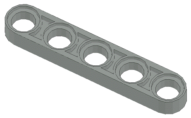
;
and two
cams (p/n 6575) 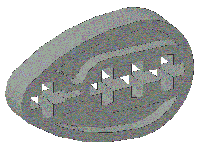

Note that there are two version of the stanchion top, p/n 3651 and p/n 32013. Either or both can be used here; one of each is shown
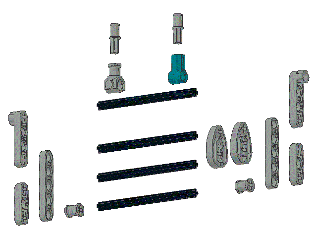
This will be the bump sensor gate for the left hand side of the robot, as viewed from inside the robot facing the IR sensors
Do not install this bump sensor gate on the robot yet
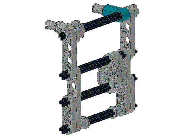
Locate a second set of the following parts and assemble them into a second bump sensor gate, as shown:
two
splined pegs (p/n 3749) 
;
two
stanchion tops (p/n 3651 or p/n 32013) 

;

two
10 unit long axles (p/n 3737) 
;
two
8 unit long axles (p/n 3707) 
;
three
collars (p/n 3713) 
;
two
4 unit long linkages (p/n 2825) 
;
two
3 unit long linkages (p/n 6632) 
;
two
5 unit long linkages (p/n 32017) 
;
and two
cams (p/n 6575) 

This will be the bump sensor gate for the right hand side of the robot, as viewed from inside the robot facing the IR sensors. Note that this is a mirror image of the left hand side bump sensor gate
Do not install this bump sensor gate on the robot yet
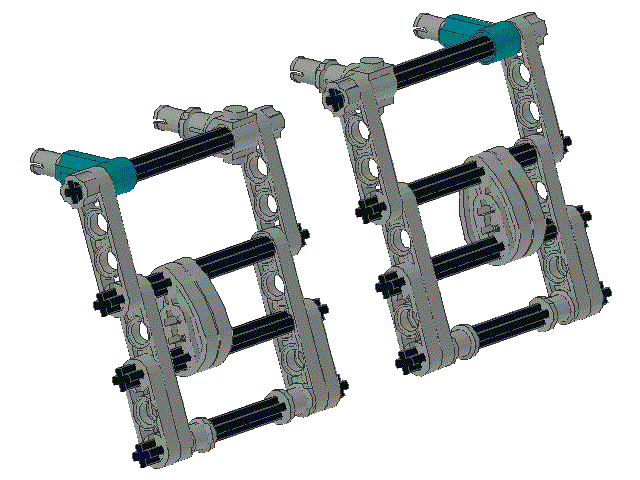
Working with one gate at a time, install the bump sensor gates on the robot by snapping the four splined pegs into the appropriate holes as shown.
Because, apart from the orientation of the stanchion tops and the splined pegs, the two gates are identical, it does not matter, so long as the stanchion tops and splined pegs are positioned correctly, which gate is on the robots left and which is on its right
Notice that on one side of the gate, the ends of the axles are, more or less, in a line whereas on the other side of the gate, they are not. The axle ends that do not line up should be toward the center of the robot.
Ensure that the top axle can rotate freely with minimal horizontal movement and that there is no contact between axles at the center of the robot.
Align the cams carefully so that they actuate the bump sensor when the gate assembly is depressed
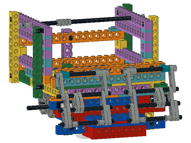 Front View
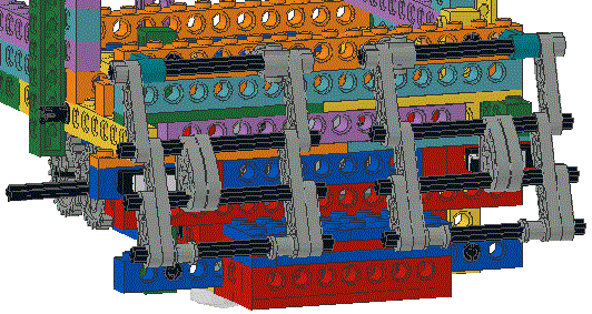 Front View Close Up
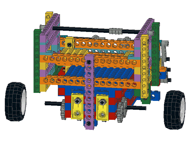
The wheels are a "friction fit" on the axles. That is, there is enough friction between the axles and the wheel's hub to keep the wheel in place.
Make sure that the wheels are pushed far enough into the wheel cavities in the robot so that they will not catch on walls and the like as the robot drives around.
But also make sure that the wheel will not touch any part of the robot as it moves.
